- Email: sales@xinfengcable.com
- WhatsApp: + 86 1 3333 8683 99
Conducting The Energy - Xinfeng Cable
Leading China Aerial MVCC Cable Manufacturer
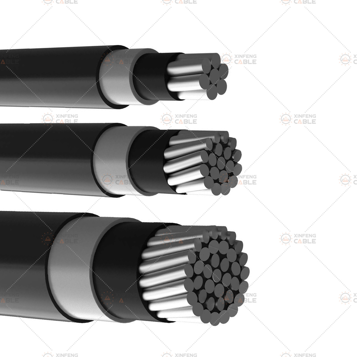
Medium Voltage Covered Conductors (MVCC) are developed to improve the reliability of the distribution of electricity. Covered conductors consist of a conductor insulated by a covering made of insulating material(s) as protection against accidental contacts with other covered conductors and with grounded parts such as tree branches etc.
IEC: 61089
IS: 398 Part-IV
BS EN: 50182/50397
IEC: 60502
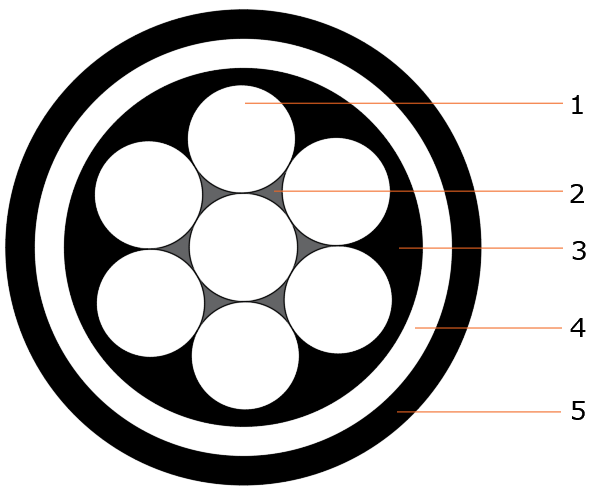
Conductor: Stranded non-compacted all aluminum alloy (AAAC) or aluminum conductor steel reinforced (ACSR).
Water Blocking Layer: Extruded, longitudinal water blocking layer (Strippable type, semiconductive, Black).
Conductor Screen: Extruded semi-conductive compound, Black.
Inner Insulation: Extruded cross linked polyethylene (XLPE, Natural).
Outer Insulation: Extruded cross linked polyethylene (UV Stabilized, Tracking & Erosion resistant XLPE, Black).
MVCC are produced in voltage rating between 6.6 KV to 33 KV.
Medium Voltage Covered Conductor(MVCC) systems can be found in South America, Africa, Asia, the Middle East,
Siberia and all across Europe. Examples of applications and reasons for choosing the amokabel covered conductor
system include:
• Forest areas – increased reliability if in contact with branches
and trees across the phases after storms
• Bird and wildlife protection areas – increased safety
• Plantations – increased reliability if in contact with branches
• Urban areas – reduced footprint due to reduced phase-to-phase distance
• Very cold climates – ice more easily released from the conductor
• Coastal areas – protects the aluminium from corrosion
• Voltage upgrades – reduced phase-to-phase distance allows the use of existing poles and crossarms
|
Conductor structure and size |
Approx. Diameter of Conductor | Thickness of Conductor screen | Thickness of Inner insulation | Thickness of Outer insulation | Approx. Cable OD. | Approx. Weight of conductor | Approx. Weight of cable | Maximum Conductor Resistance at 20°C | Approx. calculated Breaking Load |
Continuous Current Rating |
|
|
Nominal Cross Section |
Stranding & wire dia. |
||||||||||
|
mm² |
No./mm | mm | mm | mm | mm | mm | kg/km | kg/km | Ω/kM | kN | A |
|
MVCC Cable 11kV Voltage Rating |
|||||||||||
|
22 |
7/2.00 | 6.0 | 0.3 | 1.2 | 1.1 | 11.7 | 60.16 | 144 | 1.5410 | 6.45 | 115 |
| 34 | 7/2.50 | 7.5 | 0.3 | 1.2 | 1.1 | 13.2 | 94.00 | 196 | 0.9900 | 10.11 |
150 |
|
55 |
7/3.15 | 9.5 | 0.3 | 1.2 | 1.1 | 15.2 | 149.20 | 276 | 0.6210 | 16.03 | 234 |
|
80 |
7/3.81 | 11.4 | 0.3 | 1.2 | 1.1 | 17.1 | 218.26 | 372 | 0.4250 | 23.41 |
270 |
| 100 | 7/4.26 | 12.8 | 0.3 | 1.2 | 1.1 | 18.5 | 272.86 | 446 | 0.3390 | 29.26 |
325 |
|
120 |
19/2.83 | 14.2 | 0.3 | 1.2 | 1.1 | 19.9 | 329.18 | 531 | 0.2787 | 33.25 | 370 |
| 148 | 19/3.15 | 15.8 | 0.3 | 1.2 | 1.1 | 21.5 | 406.91 | 633 | 0.2290 | 43.50 |
440 |
|
232 |
19/3.94 | 19.7 | 0.3 | 1.2 | 1.1 | 25.4 | 636.67 | 922 | 0.1471 | 68.05 | 520 |
|
MVCC Cable 22kV Voltage Rating |
|||||||||||
|
22 |
7/2.00 | 6.0 | 0.3 | 1.32 | 1.1 | 11.9 | 60.16 | 149 | 1.5410 | 6.45 | 115 |
| 34 | 7/2.50 | 7.5 | 0.3 | 1.32 | 1.1 | 13.4 | 94.00 | 201 | 0.9900 | 10.11 |
150 |
|
55 |
7/3.15 | 9.5 | 0.3 | 1.32 | 1.1 | 15.4 | 149.20 | 282 | 0.6210 | 16.03 | 234 |
| 80 | 7/3.81 | 11.4 | 0.3 | 1.32 | 1.1 | 17.4 | 218.26 | 379 | 0.4250 | 23.41 |
270 |
|
100 |
7/4.26 | 12.8 | 0.3 | 1.32 | 1.1 | 18.7 | 272.86 | 453 | 0.3390 | 29.26 | 325 |
| 120 | 19/2.83 | 14.2 | 0.3 | 1.32 | 1.1 | 20.1 | 329.18 | 539 | 0.2787 | 33.25 |
370 |
|
148 |
19/3.15 | 15.8 | 0.3 | 1.32 | 1.1 | 21.7 | 406.91 | 641 | 0.2290 | 43.50 | 440 |
| 232 | 19/3.94 | 19.7 | 0.3 | 1.32 | 1.1 | 25.6 | 636.67 | 932 | 0.1471 | 68.05 |
520 |
|
MVCC Cable 33kV Voltage Rating |
|||||||||||
|
22 |
7/2.00 | 6.0 | 0.4 | 2.43 | 1.2 | 14.6 | 60.16 | 204 | 1.5410 | 6.45 | 115 |
| 34 | 7/2.50 | 7.5 | 0.4 | 2.43 | 1.2 | 16.1 | 94.00 | 262 | 0.9900 | 10.11 |
150 |
|
55 |
7/3.15 | 9.5 | 0.4 | 2.43 | 1.2 | 18.0 | 149.20 | 351 | 0.6210 | 16.03 | 234 |
| 80 | 7/3.81 | 11.4 | 0.4 | 2.43 | 1.2 | 20.0 | 218.26 | 456 | 0.4250 | 23.41 |
270 |
|
100 |
7/4.26 | 12.8 | 0.4 | 2.43 | 1.2 | 21.3 | 272.86 | 536 | 0.3390 | 29.26 | 325 |
| 120 | 19/2.83 | 14.2 | 0.4 | 2.43 | 1.2 | 22.7 | 329.18 | 628 | 0.2787 | 33.25 |
370 |
|
148 |
19/3.15 | 15.8 | 0.4 | 2.43 | 1.2 | 24.3 | 406.91 | 737 | 0.2290 | 43.50 |
440 |
| 232 | 19/3.94 | 19.7 | 0.4 | 2.43 | 1.2 | 28.3 | 636.67 | 1044 | 0.1471 | 68.05 |
520 |
|
Continuous Current Ratings are based on an ambient temperature of 40⁰C, maximum conductor temperature of 80⁰C abd solar radiation intensity of 1000 w/m2 |
|||||||||||