- Email: sales@xinfengcable.com
- WhatsApp: + 86 1 3333 8683 99
Conducting The Energy - Xinfeng Cable
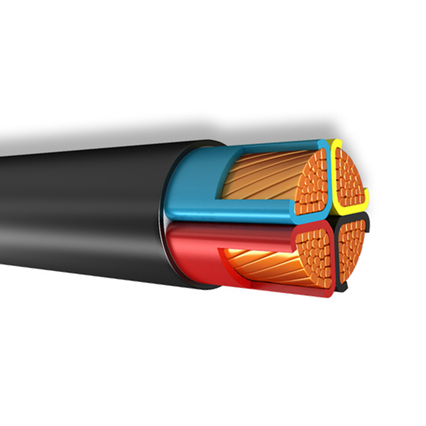
Single core or multi core pvc insulated low voltage cable
These cables are used for electricity supply in low voltage installation system, they are suitable for installation in indoors and outdoors, in cable ducts, underground, in power and switching stations, local energy distributions, industrial plants, where there is no risk of mechanical damage.
GB/12706.1, IEC60502-1, NFC 32-321, HD 603 S1 , HD 626 S1,AS/NZS 5000.1 etc.
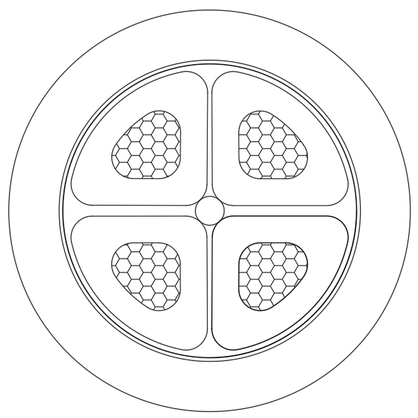
Conductor: Circular, solid, compacted or sector shaped stranded copper or aluminium
Insulation: PVC
Filler: Non-hygroscopic material
Binder tape: Non-hygroscopic material
Sheath: PVC
The product is suitable for power transmission and distribution lines with rated power frequency voltage 0.6/1 kV.
| General type | VDE type | Designation | Application |
| CU/PVC/PVC (AL/PVC/PVC) | NYY(NAYY) | Cu conductor(Al conductor)PVC insulated PVC sheathed power cable | Laying indoors, in tunnel, fixed on the bracket, pipe and buried in the soil, the cable cannot bear external mechanical forces. |
| CU/PVC/PE (AL/PVC/PE) | NY2Y(NAY2Y) | Cu conductor(Al conductor)PVC insulated PE sheathed power cable | |
| CU/PVC/STA/PVC (AL/PVC/STA/PVC) | NYBY(NAYBY) | Cu conductor(Al conductor)PVC insulated double of steel-tape armored PVC sheathed power cable | For laying indoors, in tunnel, cable trench, or direct in ground, able to bear external mechanical forces, but unable to bear large pulling force. |
| CU/PVC/STA/PE (AL/PVC/STA/PE) | NYB2Y(NAYB2Y) | Cu conductor(Al conductor)PVC insulated double of steel-tape armored PE sheathed power cable | |
| CU/PVC/ATA/PVC (AL/PVC/ATA/PVC) | NYBY(NAYBY) | Cu conductor(Al conductor)PVC insulated double of aluminium-tape armored PVC sheathed power cable | |
| CU/PVC/ATA/PE (AL/PVC/ATA/PE) | NYB2Y(NAYB2Y) | Cu conductor(Al conductor)PVC insulated double of aluminium-tape armored PE sheathed power cable | |
| CU/PVC/SWA/PVC (AL/PVC/SWA/PVC) | NYRY(NAYRY) | Cu conductor(Al conductor)PVC insulated steel-wire armored PVC sheathed power cable | For laying indoors, in tunnel, cable trench, well or direct in ground, able to bear external mechanical forces and certain pulling force. |
| CU/PVC/SWA/PE (AL/PVC/SWA/PE) | NYR2Y(NAYR2Y) | Cu conductor(Al conductor)PVC insulated steel-wire armored PE sheathed power cable | |
| CU/PVC/AWA/PVC (AL/PVC/AWA/PVC) | NYRY(NAYRY) | Cu conductor(Al conductor)PVC insulated aluminium-wire armored PVC sheathed power cable | |
| CU/PVC/AWA/PE (AL/PVC/AWA/PE) | NYR2Y(NAYR2Y) | Cu conductor(Al conductor)PVC insulated aluminium-wire armored PE sheathed power cable |
| Nominal section area mm2 |
Approx. overall diameter mm |
Approx. weight of cable kg/km |
Maximum DC resistance of the conductor Ω/km |
||
| Cu | Al | 20℃ Cu | 20℃ Al | ||
| 1×1.5 RE | 5.8 | 49.3 | – | 12.1 | – |
| 1×2.5 RE | 6.2 | 62.2 | 46.6 | 7.41 | 12.1 |
| 1×4 RE | 7.1 | 86.4 | 61.6 | 4.61 | 7.41 |
| 1×6 RE | 7.6 | 109.8 | 72.6 | 3.08 | 4.61 |
| 1×10 CC | 8.6 | 156.7 | 94.8 | 1.83 | 3.08 |
| 1×16 CC | 9.6 | 221 | 122 | 1.15 | 1.91 |
| 1×25 CC | 11.2 | 324.1 | 169.4 | 0.727 | 1.2 |
| 1×35 CC | 12.2 | 426.8 | 210.2 | 0.524 | 0.868 |
| 1×50 CC | 14 | 586 | 276.6 | 0.387 | 0.641 |
| 1×70 CC | 15.7 | 787.5 | 354.4 | 0.268 | 0.443 |
| 1×95 CC | 17.7 | 1050.5 | 462.7 | 0.193 | 0.32 |
| 1×120 CC | 19.3 | 1298.2 | 555.7 | 0.153 | 0.253 |
| 1×150 CC | 21.3 | 1611.6 | 683.6 | 0.124 | 0.206 |
| 1×185 CC | 23.6 | 1977.4 | 832.8 | 0.0991 | 0.164 |
| 1×240 CC | 26.4 | 2537.7 | 1052.9 | 0.0754 | 0.125 |
| 1×300 CC | 29.1 | 3146.2 | 1290.1 | 0.0601 | 0.1 |
| 1×400 CC | 32.7 | 4140.8 | 1666 | 0.047 | 0.0778 |
| 1×500 CC | 36.3 | 5142.2 | 2048.7 | 0.0366 | 0.0605 |
| 1×630 CC | 40 | 6395.4 | 2497.6 | 0.0283 | 0.0469 |
| 2×1.5 RE | 10.2 | 117.6 | – | 12.1 | – |
| 2×2.5 RE | 11 | 145.3 | 114.2 | 7.41 | 12.1 |
| 2×4 RE | 12.7 | 202.6 | 152.9 | 4.61 | 7.41 |
| 2×6 RE | 13.7 | 257 | 182.4 | 3.08 | 4.61 |
| 2×10 CC | 15.8 | 384 | 259.6 | 1.83 | 3.08 |
| 2×16 CC | 17.8 | 517.5 | 318.5 | 1.15 | 1.91 |
| 2×25 CC | 21 | 731.8 | 420.9 | 0.727 | 1.2 |
| 2×35 CC | 23 | 938.6 | 503.3 | 0.524 | 0.868 |
| 2×50 SM | 20.8 | 1184.9 | 563.1 | 0.387 | 0.641 |
| 2×70 SM | 23.2 | 1588.5 | 718 | 0.268 | 0.443 |
| 2×95 SM | 26.8 | 2128.3 | 946.9 | 0.193 | 0.32 |
| 2×120 SM | 29 | 2627.1 | 1134.8 | 0.153 | 0.253 |
| 2×150 SM | 32.3 | 3264.7 | 1399.3 | 0.124 | 0.206 |
| 2×185 SM | 35.6 | 4003.7 | 1703 | 0.0991 | 0.164 |
| 2×240 SM | 39.8 | 5143.2 | 2158.6 | 0.0754 | 0.125 |
| 2×300 SM | 44.3 | 6385.8 | 2655.1 | 0.0601 | 0.1 |
| 3×1.5 RE | 10.6 | 147 | – | 12.1 | – |
| 3×2.5 RE | 11.5 | 185.6 | 138.9 | 7.41 | 12.1 |
| 3×4 RE | 13.4 | 258.1 | 183.5 | 4.61 | 7.41 |
| 3×6 RE | 14.5 | 338.2 | 226.3 | 3.08 | 4.61 |
| 3×10 CC | 16.7 | 489 | 302.4 | 1.83 | 3.08 |
| 3×16 CC | 18.9 | 703.1 | 404.6 | 1.15 | 1.91 |
| 3×25 CC | 22.3 | 1012.9 | 546.5 | 0.727 | 1.2 |
| 3×35 CC | 24.5 | 1315.8 | 663 | 0.524 | 0.868 |
| 3×50 SM | 23.9 | 1734.6 | 801.9 | 0.387 | 0.641 |
| 3×70 SM | 27.1 | 2337.7 | 1031.9 | 0.268 | 0.443 |
| 3×95 SM | 31 | 3130.7 | 1358.6 | 0.193 | 0.32 |
| 3×120 SM | 34.3 | 3878.7 | 1640.3 | 0.153 | 0.253 |
| 3×150 SM | 38.6 | 4827.9 | 2029.9 | 0.124 | 0.206 |
| 3×185 SM | 42.7 | 5929.1 | 2478.1 | 0.0991 | 0.164 |
| 3×240 SM | 48 | 7621.4 | 3144.5 | 0.0754 | 0.125 |
| 3×300 SM | 53.2 | 9463.7 | 3867.6 | 0.0601 | 0.1 |
| 4×1.5 RE | 11.4 | 177 | – | 12.1 | – |
| 4×2.5 RE | 12.4 | 226.9 | 164.7 | 7.41 | 12.1 |
| 4×4 RE | 14.5 | 320.2 | 220.7 | 4.61 | 7.41 |
| 4×6 RE | 15.7 | 424.1 | 274.9 | 3.08 | 4.61 |
| 4×10 CC | 18.2 | 607.6 | 358.9 | 1.83 | 3.08 |
| 4×16 CC | 20.6 | 861 | 463.1 | 1.15 | 1.91 |
| 4×25 CC | 24.5 | 1287.4 | 665.6 | 0.727 | 1.2 |
| 4×35 CC | 26.9 | 1687.4 | 816.9 | 0.524 | 0.868 |
| 4×50 SM | 28 | 2295.4 | 1051.8 | 0.387 | 0.641 |
| 4×70 SM | 31.6 | 3095.1 | 1354.1 | 0.268 | 0.443 |
| 4×95 SM | 35.9 | 4146 | 1783.2 | 0.193 | 0.32 |
| 4×120 SM | 38.5 | 5125.7 | 2141.1 | 0.153 | 0.253 |
| 4×150 SM | 42.8 | 6379.9 | 2649.2 | 0.124 | 0.206 |
| 4×185 SM | 48.4 | 7849.2 | 3248 | 0.0991 | 0.164 |
| 4×240 SM | 53.5 | 10084 | 4114.8 | 0.0754 | 0.125 |
| 4×300 SM | 59.2 | 12526.3 | 5064.8 | 0.0601 | 0.1 |
| 5×1.5 RE | 12.2 | 207.7 | – | 12.1 | – |
| 5×2.5 RE | 13.3 | 268.9 | 191.2 | 7.41 | 12.1 |
| 5×4 RE | 15.7 | 383.2 | 258.9 | 4.61 | 7.41 |
| 5×6 RE | 17.1 | 511.1 | 324.6 | 3.08 | 4.61 |
| 5×10 CC | 19.9 | 742.2 | 431.3 | 1.83 | 3.08 |
| 5×16 CC | 22.6 | 1056.3 | 558.8 | 1.15 | 1.91 |
| 5×25 CC | 26.9 | 1577.9 | 800.7 | 0.727 | 1.2 |
| 5×35 CC | 29.6 | 2075.3 | 987.1 | 0.524 | 0.868 |
| 5×50 SM | 34.2 | 2842.8 | 1288.3 | 0.387 | 0.641 |
| 5×70 SM | 39.4 | 3837.2 | 1660.9 | 0.268 | 0.443 |
| 5×95 SM | 44.5 | 5150.7 | 2197.2 | 0.193 | 0.32 |
| 5×120 SM | 48.7 | 6376.4 | 2645.6 | 0.153 | 0.253 |
| 5×150 SM | 54.3 | 7948.1 | 3284.7 | 0.124 | 0.206 |
| 5×185 SM | 60.3 | 9762.5 | 4011 | 0.0991 | 0.164 |
| 5×240 SM | 67.8 | 12568.1 | 5106.6 | 0.0754 | 0.125 |
| 5×300 SM | 74.9 | 15616.3 | 6289.4 | 0.0601 | 0.1 |
| Nominal section area mm2 |
Approx. overall diameter mm |
Approx. weight of cable kg/km |
Maximum DC resistance of the conductor Ω/km |
||||
| Cu | Al | 20℃ Cu | 20℃ Al | ||||
| 3×4+1×2.5 RE | 13.9 | 296.9 | 206.7 | 4.61 | 7.41 | 7.41 | 12.1 |
| 3×6+1×4 RE | 15.4 | 401.3 | 264.5 | 3.08 | 4.61 | 4.61 | 7.41 |
| 3×10+1×6 CC | 17.6 | 566.3 | 342.4 | 1.83 | 3.08 | 3.08 | 4.61 |
| 3×16+1×10 CC | 20 | 802.2 | 441.6 | 1.15 | 1.83 | 1.91 | 3.08 |
| 3×25+1×16 CC | 23.5 | 1185.7 | 619.9 | 0.727 | 1.15 | 1.2 | 1.91 |
| 3×35+1×16 CC | 25.3 | 1485.7 | 733.4 | 0.524 | 1.15 | 0.868 | 1.91 |
| 3×50+1×25 SM | 26.9 | 2048.5 | 960.3 | 0.387 | 0.727 | 0.641 | 1.2 |
| 3×70+1×35 SM | 30.2 | 2750.6 | 1227.2 | 0.268 | 0.524 | 0.443 | 0.868 |
| 3×95+1×50 SM | 34.3 | 3701.9 | 1618.9 | 0.193 | 0.387 | 0.32 | 0.641 |
| 3×120+1×70 SM | 36.8 | 4633.9 | 1960.1 | 0.153 | 0.268 | 0.253 | 0.443 |
| 3×150+1×70 SM | 40.8 | 5579.1 | 2345.8 | 0.124 | 0.268 | 0.206 | 0.443 |
| 3×185+1×95 SM | 46.1 | 6947.4 | 2905.8 | 0.0991 | 0.193 | 0.164 | 0.32 |
| 3×240+1×120 SM | 50.9 | 8872.3 | 3649.2 | 0.0754 | 0.153 | 0.125 | 0.253 |
| 3×300+1×150 SM | 56.3 | 11018.3 | 4489.5 | 0.0601 | 0.124 | 0.1 | 0.206 |
| 4×4+1×2.5 RE | 15.2 | 360.4 | 245.3 | 4.61 | 7.41 | 7.41 | 12.1 |
| 4×6+1×4 RE | 16.8 | 488.6 | 314.5 | 3.08 | 4.61 | 4.61 | 7.41 |
| 4×10+1×6 CC | 19.3 | 696.9 | 410.9 | 1.83 | 3.08 | 3.08 | 4.61 |
| 4×16+1×10 CC | 22 | 993.4 | 533.3 | 1.15 | 1.83 | 1.91 | 3.08 |
| 4×25+1×16 CC | 26 | 1477.1 | 755.8 | 0.727 | 1.15 | 1.2 | 1.91 |
| 4×35+1×16 CC | 28.2 | 1875 | 905 | 0.524 | 1.15 | 0.868 | 1.91 |
| 4×50+1×25 SM | 27.8 | 2561.8 | 1162.8 | 0.387 | 0.727 | 0.641 | 1.2 |
| 4×70+1×35 SM | 31 | 3455.2 | 1496.5 | 0.268 | 0.524 | 0.443 | 0.868 |
| 4×95+1×50 SM | 35.7 | 4662.6 | 1988.9 | 0.193 | 0.387 | 0.32 | 0.641 |
| 4×120+1×70 SM | 39.1 | 5842.8 | 2423 | 0.153 | 0.268 | 0.253 | 0.443 |
| 4×150+1×70 SM | 42.8 | 7089.1 | 2923 | 0.124 | 0.268 | 0.206 | 0.443 |
| 4×185+1×95 SM | 47.7 | 8802.6 | 3610.6 | 0.0991 | 0.193 | 0.164 | 0.32 |
| 4×240+1×120 SM | 53.5 | 11283.2 | 4567.8 | 0.0754 | 0.153 | 0.125 | 0.253 |
| 4×300+1×150 SM | 59.3 | 14029 | 5634.7 | 0.0601 | 0.124 | 0.1 | 0.206 |
| 3×4+2×2.5 RE | 14.7 | 337.5 | 231.8 | 4.61 | 7.41 | 7.41 | 12.1 |
| 3×6+2×4 RE | 16.5 | 466 | 304.3 | 3.08 | 4.61 | 4.61 | 7.41 |
| 3×10+2×6 CC | 18.7 | 651.6 | 390.4 | 1.83 | 3.08 | 3.08 | 4.61 |
| 3×16+2×10 CC | 21.5 | 930.6 | 507.8 | 1.15 | 1.83 | 1.91 | 3.08 |
| 3×25+2×16 CC | 25.2 | 1376.3 | 711 | 0.727 | 1.15 | 1.2 | 1.91 |
| 3×35+2×16 CC | 26.8 | 1674.7 | 822.8 | 0.524 | 1.15 | 0.868 | 1.91 |
| 3×50+2×25 SM | 27.7 | 2325.2 | 1081.6 | 0.387 | 0.727 | 0.641 | 1.2 |
| 3×70+2×35 SM | 30.9 | 3123.8 | 1382.7 | 0.268 | 0.524 | 0.443 | 0.868 |
| 3×95+2×50 SM | 35.6 | 4232.7 | 1838.8 | 0.193 | 0.387 | 0.32 | 0.641 |
| 3×120+2×70 SM | 38.9 | 5368.1 | 2259.2 | 0.153 | 0.268 | 0.253 | 0.443 |
| 3×150+2×70 SM | 42.6 | 6312.2 | 2643.6 | 0.124 | 0.268 | 0.206 | 0.443 |
| 3×185+2×95 SM | 47.5 | 7927.8 | 3295.4 | 0.0991 | 0.193 | 0.164 | 0.32 |
| 3×240+2×120 SM | 53.2 | 10103.9 | 4134.7 | 0.0754 | 0.153 | 0.125 | 0.253 |
| 3×300+2×150 SM | 59.1 | 12560.6 | 5099.1 | 0.0601 | 0.124 | 0.1 | 0.206 |
No. of cores: 1, 2, 3, 4, 5, 2+E, 3+E, 4+E;
Nominal cross-section (mm2): 0.5 ~ 800;